\(\renewcommand{\AA}{\text{Å}}\)
compute xrd command
Syntax
compute ID group-ID xrd lambda type1 type2 ... typeN keyword value ...
ID, group-ID are documented in compute command
xrd = style name of this compute command
lambda = wavelength of incident radiation (length units)
type1 type2 … typeN = chemical symbol of each atom type (see valid options below)
zero or more keyword/value pairs may be appended
keyword = 2Theta or c or LP or manual or echo
2Theta values = Min2Theta Max2Theta
  Min2Theta,Max2Theta = minimum and maximum 2 theta range to explore
  (radians or degrees)
c values = c1 c2 c3
  c1,c2,c3 = parameters to adjust the spacing of the reciprocal
             lattice nodes in the h, k, and l directions respectively
LP value = switch to apply Lorentz-polarization factor
  0/1 = off/on
manual = flag to use manual spacing of reciprocal lattice points
           based on the values of the c parameters
echo = flag to provide extra output for debugging purposes
Examples
compute 1 all xrd 1.541838 Al O 2Theta 0.087 0.87 c 1 1 1 LP 1 echo
compute 2 all xrd 1.541838 Al O 2Theta 10 100 c 0.05 0.05 0.05 LP 1 manual

fix 1 all ave/histo/weight 1 1 1 0.087 0.87 250 c_1[1] c_1[2] mode vector file Rad2Theta.xrd
fix 2 all ave/histo/weight 1 1 1 10 100 250 c_2[1] c_2[2] mode vector file Deg2Theta.xrd
Description
Define a computation that calculates X-ray diffraction intensity as described in (Coleman) on a mesh of reciprocal lattice nodes defined by the entire simulation domain (or manually) using a simulated radiation of wavelength lambda.
The X-ray diffraction intensity, \(I\), at each reciprocal lattice point, \(k\), is computed from the structure factor, \(F\), using the equations:
Here, \(\mathbf{k}\) is the location of the reciprocal lattice node, \(r_j\) is the position of each atom, \(f_j\) are atomic scattering factors, Lp is the Lorentz-polarization factor, and \(\theta\) is the scattering angle of diffraction. The Lorentz-polarization factor can be turned off using the optional LP keyword.
Diffraction intensities are calculated on a three-dimensional mesh of reciprocal lattice nodes. The mesh spacing is defined either (a) by the entire simulation domain or (b) manually using selected values as shown in the 2D diagram below.
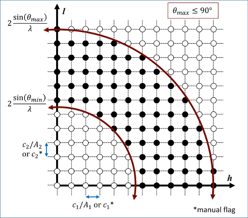
For a mesh defined by the simulation domain, a rectilinear grid is constructed with spacing \(c A^{-1}\) along each reciprocal lattice axis, where \(A\) is a matrix containing the vectors corresponding to the edges of the simulation cell. If one or two directions has non-periodic boundary conditions, then the spacing in these directions is defined from the average of the (inversed) box lengths with periodic boundary conditions. Meshes defined by the simulation domain must contain at least one periodic boundary.
If the manual flag is included, the mesh of reciprocal lattice nodes will be defined using the c values for the spacing along each reciprocal lattice axis. Note that manual mapping of the reciprocal space mesh is good for comparing diffraction results from multiple simulations; however, it can reduce the likelihood that Bragg reflections will be satisfied unless small spacing parameters (\(< 0.05~\AA^{-1}\)) are implemented. Meshes with manual spacing do not require a periodic boundary.
The limits of the reciprocal lattice mesh are determined by range of scattering angles explored. The 2Theta parameter allows the user to reduce the scattering angle range to only the region of interest which reduces the cost of the computation.
The atomic scattering factor, \(f_j\), accounts for the reduction in diffraction intensity due to Compton scattering. Compute xrd uses analytical approximations of the atomic scattering factors that vary for each atom type (type1 type2 … typeN) and angle of diffraction. The analytic approximation is computed using the formula (Colliex):
Coefficients parameterized by (Peng) are assigned for each atom type designating the chemical symbol and charge of each atom type. Valid chemical symbols for compute xrd are:
H |
He1- |
He |
Li |
Li1+ |
Be |
Be2+ |
B |
C |
Cval |
N |
O |
O1- |
F |
F1- |
Ne |
Na |
Na1+ |
Mg |
Mg2+ |
Al |
Al3+ |
Si |
Sival |
Si4+ |
P |
S |
Cl |
Cl1- |
Ar |
K |
Ca |
Ca2+ |
Sc |
Sc3+ |
Ti |
Ti2+ |
Ti3+ |
Ti4+ |
V |
V2+ |
V3+ |
V5+ |
Cr |
Cr2+ |
Cr3+ |
Mn |
Mn2+ |
Mn3+ |
Mn4+ |
Fe |
Fe2+ |
Fe3+ |
Co |
Co2+ |
Co |
Ni |
Ni2+ |
Ni3+ |
Cu |
Cu1+ |
Cu2+ |
Zn |
Zn2+ |
Ga |
Ga3+ |
Ge |
Ge4+ |
As |
Se |
Br |
Br1- |
Kr |
Rb |
Rb1+ |
Sr |
Sr2+ |
Y |
Y3+ |
Zr |
Zr4+ |
Nb |
Nb3+ |
Nb5+ |
Mo |
Mo3+ |
Mo5+ |
Mo6+ |
Tc |
Ru |
Ru3+ |
Ru4+ |
Rh |
Rh3+ |
Rh4+ |
Pd |
Pd2+ |
Pd4+ |
Ag |
Ag1+ |
Ag2+ |
Cd |
Cd2+ |
In |
In3+ |
Sn |
Sn2+ |
Sn4+ |
Sb |
Sb3+ |
Sb5+ |
Te |
I |
I1- |
Xe |
Cs |
Cs1+ |
Ba |
Ba2+ |
La |
La3+ |
Ce |
Ce3+ |
Ce4+ |
Pr |
Pr3+ |
Pr4+ |
Nd |
Nd3+ |
Pm |
Pm3+ |
Sm |
Sm3+ |
Eu |
Eu2+ |
Eu3+ |
Gd |
Gd3+ |
Tb |
Tb3+ |
Dy |
Dy3+ |
Ho |
Ho3+ |
Er |
Er3+ |
Tm |
Tm3+ |
Yb |
Yb2+ |
Yb3+ |
Lu |
Lu3+ |
Hf |
Hf4+ |
Ta |
Ta5+ |
W |
W6+ |
Re |
Os |
Os4+ |
Ir |
Ir3+ |
Ir4+ |
Pt |
Pt2+ |
Pt4+ |
Au |
Au1+ |
Au3+ |
Hg |
Hg1+ |
Hg2+ |
Tl |
Tl1+ |
Tl3+ |
Pb |
Pb2+ |
Pb4+ |
Bi |
Bi3+ |
Bi5+ |
Po |
At |
Rn |
Fr |
Ra |
Ra2+ |
Ac |
Ac3+ |
Th |
Th4+ |
Pa |
U |
U3+ |
U4+ |
U6+ |
Np |
Np3+ |
Np4+ |
Np6+ |
Pu |
Pu3+ |
Pu4+ |
Pu6+ |
Am |
Cm |
Bk |
Cf |
If the echo keyword is specified, compute xrd will provide extra reporting information to the screen.
Output info
This compute calculates a global array. The number of rows in the array is the number of reciprocal lattice nodes that are explored which by the mesh. The global array has two columns.
The first column contains the diffraction angle in the units (radians or degrees) provided with the 2Theta values. The second column contains the computed diffraction intensities as described above.
The array can be accessed by any command that uses global values from a compute as input. See the Howto output doc page for an overview of LAMMPS output options.
All array values calculated by this compute are “intensive”.
Restrictions
This compute is part of the DIFFRACTION package. It is only enabled if LAMMPS was built with that package. See the Build package page for more info.
The compute_xrd command does not work for triclinic cells.
Default
The option defaults are 2Theta = 1 179 (degrees), c = 1 1 1, LP = 1, no manual flag, no echo flag.
(Coleman) Coleman, Spearot, Capolungo, MSMSE, 21, 055020 (2013).
(Colliex) Colliex et al. International Tables for Crystallography Volume C: Mathematical and Chemical Tables, 249-429 (2004).
(Peng) Peng, Ren, Dudarev, Whelan, Acta Crystallogr. A, 52, 257-76 (1996).