\(\renewcommand{\AA}{\text{Å}}\)
fix graphics command
Syntax
fix ID group-ID graphics Nevery keyword args ...
ID, group-ID are documented in fix command
graphics = style name of this fix command
Nevery = update graphics information every this many time steps
one or more keyword/args pairs may be appended
keyword = sphere or cylinder or arrow or progbar
sphere args = type x y z R
  type = an atom type value to select the color of the sphere
  x, y, z = position of the center of the sphere (distance units)
  R = sphere radius (distance units)
  any of x, y, z, and R can be a variable (see below)
cylinder args = type x1 y1 z1 x2 y2 z2 R
  type = an atom type value to select the color of the sphere
  x1, y1, z1, x2, y2, z2 = positions of the centers at the two ends of the cylinder (distance units)
  R = cylinder radius (distance units)
  any of x1, y1, z1, x2, y2, z2, and R can be a variable (see below)
arrow args = type x1 y1 z1 x2 y2 z2 R ratio
  type = an atom type value to select the color of the sphere
  x1, y1, z1, x2, y2, z2 = positions of the centers at the tip and the bottom of the arrow (distance units)
  R = cylinder radius (distance units)
  ratio = tip to body ratio (unitless)
  any of x1, y1, z1, x2, y2, z2, and R can be a variable (see below)
progbar args = type1 type2 dim x y z length R ratio tics
  type1 = an atom type value to select the color of the progress bar body and the tics
  type2 = an atom type value to select the color of the progress indicator
  dim = x or y or z, direction of the progress bar
  x, y, z = position of the progress bar center (distance units)
  length = length of progress bar (distance units)
  R = cylinder radius (distance units)
  ratio = progress status (unitless)
  tics = number of tics (unitless)
  only the progress ratio value can be a variable (see below)
Examples
fix 1 all graphics 100 sphere 1 0.0 0.0 15.0 3.0 sphere 2 0.0 0.0 5.0 1.0
fix 1 all graphics 1000 sphere 1 v_x v_y 0.0 v_radius cylinder 1 v_x v_y 0.0 v_x v_y 10.0 3.0
fix 2 all graphics 100 progbar 3 1 z 0.012 -0.012 0.0025 0.03 0.0003 v_prog 10
Description
Added in version TBD.
This fix allows to add arbitrary objects to images rendered with dump image using the fix keyword.
The Nevery keyword determines how often the graphics object data is updated. This should be the same value as the corresponding N parameter of the dump image command. LAMMPS will stop with an error message if the settings for this fix and the dump command are not compatible.
Available graphics objects are (see above for exact command line syntax):
sphere - a sphere defined by its center location and its radius
cylinder - a cylinder defined by its two center endpoints and its radius
arrow - a cylinder with a cone at one side (see note below)
progbar - progress bar a long a selected axis and with optional tick marks
The type quantity determines the color of the object. Its represents an atom type and the object will be colored the same as the corresponding atom type when the type coloring scheme is used in the dump image fix command is used. The color may also be that of the atom type’s element or just a globally set constant color for all objects of this fix instance, which can be changed using a dump modify fcolor command. For the progbar object two atom type values must be specified.
The x, y, and z parameters correspond to the position of the center of the object (sphere and progbar). x1, y1, and z1 as well as x2, y2, and z2 are instead representing the top and bottom position of a graphics object (cylinder and arrow). The R parameter determines the radius.
The progbar object has four additional parameters: dim sets the direction of the progress bar, “x”, “y”, or “z”; length sets the length of the entire object; ratio sets the ratio of progress and is expected to be between 0.0 and 1.0 (larger or smaller values will be reset to 1.0 or 0.0, respectively); and tics determines the number of tics shown on the progress bar, this must be a number between 0 and 20. Unlike for the other graphics objects, all settings except for ratio are fixed and cannot be a variable reference.
Work in progress notice
The arrow object is currently composed of two cylinders since the dump image render implementation is missing a primitive to render a cone. This fix will be updated when that functionality becomes available.
Many of the quantities defining a graphics object can be specified as an equal-style variable, namely x, y, z, or R for a sphere or namely x1, y1, z1, x2, y2, z2, or R for a cylinder. If any of these values is a variable, it should be specified as v_name, where name is the variable name. In this case, the variable will be evaluated each Nevery timestep, and its value used to define the indenter geometry.
Note that equal-style variables can specify formulas with various mathematical functions, and include thermo_style command keywords for the simulation box parameters and timestep and elapsed time. Thus it is easy to specify graphics object properties like position, orientation, radius or more that change as a function of time or span consecutive runs in a continuous fashion. For the latter, see the start and stop keywords of the run command and the elaplong keyword of thermo_style custom for details.
For example, if a sphere’s x-position is specified as v_x, then this variable definition will keep its center at a relative position in the simulation box, 1/4 of the way from the left edge to the right edge, even if the box size changes:
variable x equal "xlo + 0.25*lx"
Similarly, either of these variable definitions will move the sphere from an initial position at 2.5 at a constant velocity of 5:
variable x equal "2.5 + 5*elaplong*dt"
variable x equal vdisplace(2.5,5)
If a sphere’s radius is specified as v_r, then these variable definitions will grow the size of the sphere at a specified rate.
variable r0 equal 0.0
variable rate equal 1.0
variable r equal "v_r0 + step*dt*v_rate"
Dump image info
Added in version TBD.
Fix graphics is designed to be used with the fix keyword of dump image. The fix will pass geometry information about the objects listed on the command line to dump image so that they are included in the rendered image.
The fflag1 setting of dump image fix determines whether cylinder elements are capped with spheres: 0 means no caps, 1 means the lower end is capped, 2 means the upper end is capped, and 3 means both ends are capped. This applies to the cylinder object and also to the body of the arrow object and the elements of the progbar object.
The fflag2 setting allows you to adjust the radius of the rendered sphere and cylinder items comprising the objects. Since the radius of these objects is an input parameter for this fix, it is recommended to set this flag to 0.0.
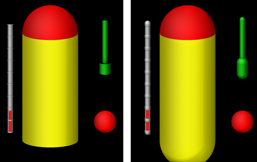
Example of graphics objects rendered with fix graphics with fflag1 setting of 0 (left) and 3 (right)
These images were created with the following input file:
units           si
region      simulation_box block -0.01 0.01 -0.01 0.01 -0.01 0.01 units box
create_box 4 simulation_box
mass * 1

variable xpos equal 0.004*sin(PI*step/1000)
variable ypos equal 0.004*cos(PI*step/1000)
variable zpos equal 5.0*v_xpos
variable prog equal (step)/10000.0
fix gra all graphics 50 sphere 1 v_xpos v_ypos -0.009 0.002 &
                        sphere 1 0.01 -0.005 0.01 0.005 &
                        progbar 3 1 z 0.012 -0.012 0.002 0.02 0.0005 v_prog 10 &
                        cylinder 4 0.01 -0.005 -0.01 0.01 -0.005 0.01 0.005  &
                        arrow 2 v_xpos v_ypos 0.0 v_xpos v_ypos 0.01 0.0005 0.2

dump viz all image 100 myimage2-*.ppm type type size 600 600 zoom 1.24872 &
              shiny 0.2 fsaa yes ssao yes 4539 0.6 box no 0.01 axes no 0.5 0.025 &
              fix gra type 0 0 view 75 5
dump_modify viz pad 9 backcolor black  acolor 3 gray

run 2000
Restart, fix_modify, output, run start/stop, minimize info
No information about this fix is written to binary restart files.
None of the fix_modify options apply to this fix.
Restrictions
none
Default
none